
Annonces OpenDeck
Alerte nouvelle annonceForums Shantea Controls OpenDeck
News
Images


Fiche technique
- Fabricant : Shantea Controls
- Modèle : OpenDeck
- Catégorie : Autres Contrôleurs MIDI
- Fiche créée le : 17/02/2017
Projet DIY hardware et software en open source pour concevoir ses propres contrôleurs MIDI
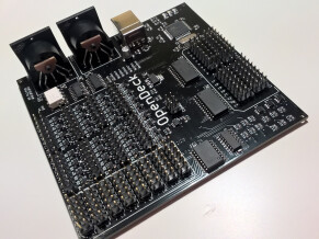
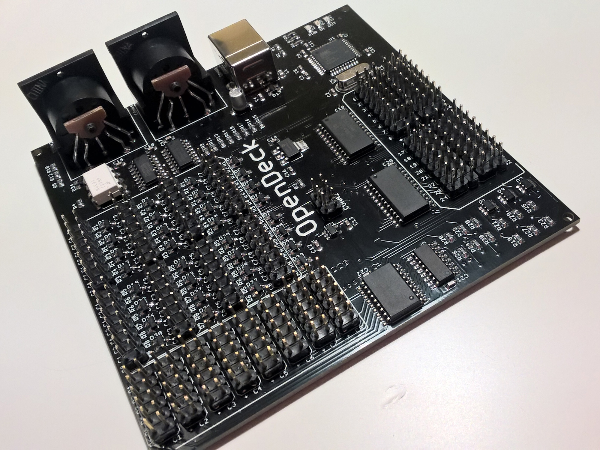
OpenDeck is a platform suited both for prototyping and developing custom MIDI controllers compatible with any MIDI software on any OS. Main part of the platform is board on which various components used to build a MIDI controller can be connected. The board supports the following components:
- Buttons
- Encoders
- LEDs (single color or RGB)
- Potentiometers
- FSRs (force-sensitive resistors)
Communication via SysEx messages
WebMIDI platform for programming
You can connect various components which are the building blocks of your MIDI controller into OpenDeck board. It allows you to connect:
- 64 buttons or 32 encoders max (one encoder is kinda like having two buttons)
- 32 potentiometers or FSRs (force-sensitive resistors) – support for other analog sensors is planned as well
- 48 single color or 16 RGB LEDs
The board also contains DIN MIDI in and out ports. MIDI in port can be used in two ways:
- MIDI to USB converter, allowing you to receive data from MIDI gear and translate it to USB MIDI to control your MIDI software on a computer
- LED control, allowing you to receive data from MIDI gear and control LEDs connected to OpenDeck board.
Schematic
Complete schematic and PCB files can be found on this link.
Power
The board has only one power connector – USB (B type). Board can be used either using computer or standalone, in which case USB wall charger is required – any one will do, as long as it meets USB power spec (5V/500mA).
ESD protection
USB data and voltage lines have ESD protection diodes. There’s a nice article on electro-static discharge on Wikipedia.
Indicator LEDs
There are two LEDs on board – power and bootloader LEDs. Power LED is constantly on when board is powered on, while bootloader LED is only active when firmware update is in progress.
Microcontroller
The brain of OpenDeck board is same microcontroller used in Arduino Leonardo and Teensy 2.0 – Atmel ATmega 32u4. That little microcontroller has USB hardware built right into the chip which allows your computer to recognize it as generic MIDI device, so that there are no drivers required on any major platform (Linux, Mac OS X, Windows).
Button/encoder hardware
In order to read buttons and encoders, a matrix setup is used. There are 8 input rows controlled by 74HC165 shift register and 8 columns controlled by 74HC238 decoder. Matrix uses column-switching to read data and there is only one active column at time during which all 8 rows are being read. There is more info on how button (and LED) matrix works on this link.
LED hardware
LED setup also uses matrix. It has 6 rows and 8 columns. Driving LED matrix directly from microcontroller is generally un-advisable, since the microcontroller isn’t really meant to be current source (or sink) so its capabilities are quite limited in that regard. Matrix can draw a lot of current, so if not careful, you can easily damage the microcontroller. In order to solve this, several components are used:
- LED hardware uses dedicated voltage regulator, LP2985-N. Regulator outputs stable 4V.
- Each LED row has a MOSFET transistor which turns the row on or off, triggered by a state of digital pin on microcontroller. This way, very little current is required to turn the MOSFET on, and when it is on, transistor draws the current from 4V voltage regulator instead of microcontroller, and feeds it into LED.
- Each column is connected to ULN2803 current sink, since 6 rows of LEDs can generate about 200mA of current and absolute maximum microcontroller can handle is 40mA.
- Current sink inputs are connected to another 74HC238 decoder so that only 3 pins are required to handle column switching instead of 8.
The big question here was which resistors to choose for LED rows. In order to achieve full brightness, most LEDs require 20mA of current. In matrix, LEDs get switched on and off very fast without you noticing it. Current flawing through LEDs in matrix is called “pulse” current, since it flaws for a very short period of time. If you would pick a resistor for 20mA of current in LED matrix, you would notice that LED isn’t really set to maximum brightness, since the current is actually lower. Because of this, we will calculate the value of resistor to achieve 30mA of current. Another problem rises here: each color of LED has different voltage drop. For instance, red LED usually has voltage drop around 1.7V. Green has around 2.2V. In order to select resistor value, I took the average voltage drop for most popular colors, based on this table. The average drop is 2.3V. For 30mA current, 4V voltage source and 2.3V of voltage drop, a resistor value of 56 ohms is chosen. Since this calculation is based on average voltage drop, the current will vary depending on chosen color.
Analog hardware
For analog components to work reliably, stable voltage is absolutely required. Like LED hardware, analog part of the board also has dedicated 3.3V voltage regulator, MCP1825. To read values from 32 analog components, two 4067 analog multiplexers are used.
MIDI hardware
MIDI in hardware requires the use of opto-coupler – I’ve selected 6N138 as recommended on MIDIbox forums and official MIDI documentation. MIDI out circuit is the same as recommended on Teensy web site.
Autres catégories dans Surfaces de contrôle MIDI


Autres dénominations : open deck