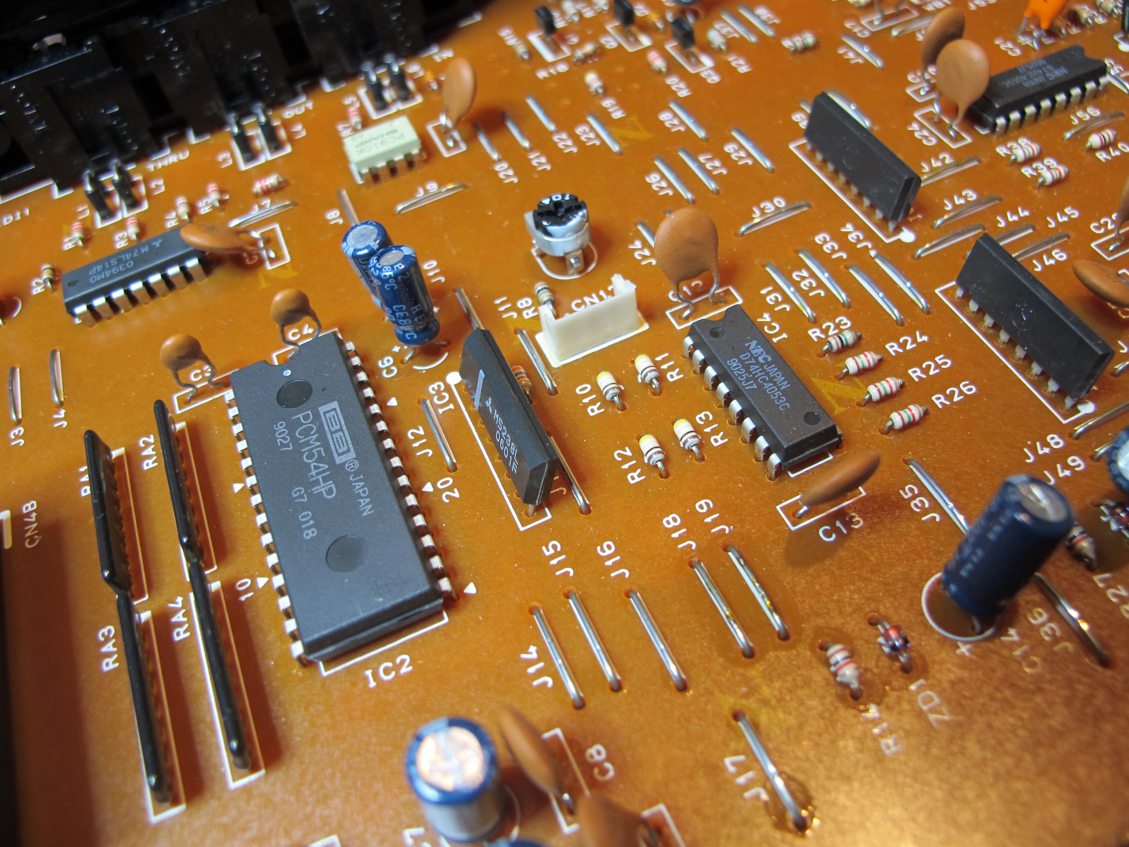
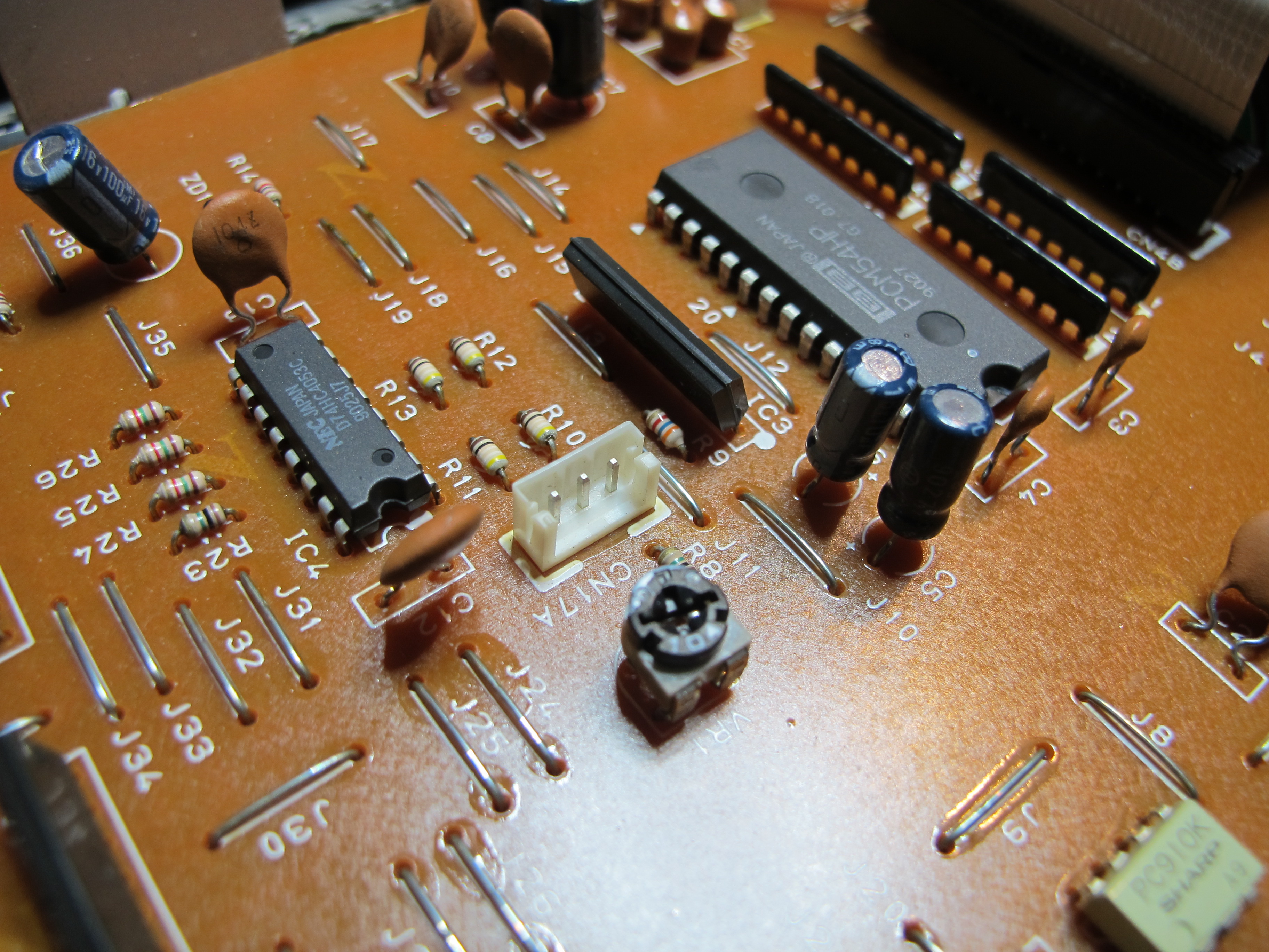
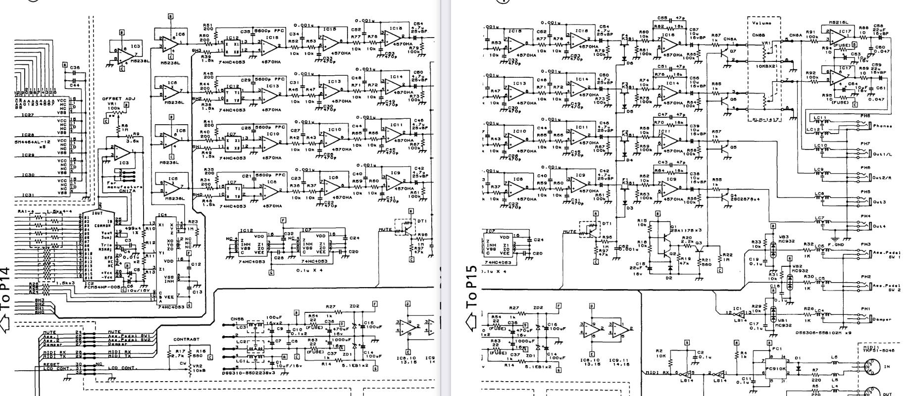
DAC 16+3bits du Korg Wavestation
- 1 réponse
- 1 participant
- 343 vues
- 1 follower
.: Odon Quelconque :.
12569

Drogué·e à l’AFéine
Membre depuis 24 ans
.: Odon Quelconque :.
12569
Drogué·e à l’AFéine
Membre depuis 24 ans
- < Liste des sujets
- Charte