Monotribe pitch the kick
- 45 réponses
- 13 participants
- 16 009 vues
- 14 followers
profx
Korg ayant fourni la schéma électrique, cela devrait être facile. Mais comme je ne souhaite pas trop cramer le circuit, je passe vous demander votre avis.
Source :
http://electro-music.com/forum/topic-56718.html
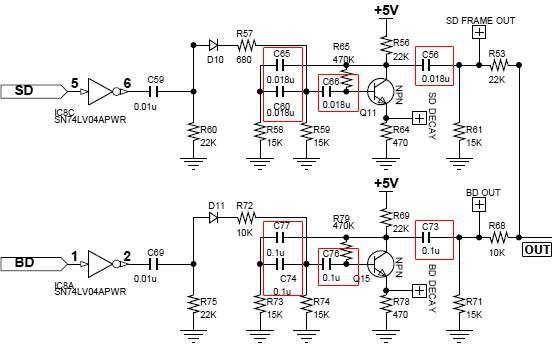
Ce qui est flagrant entre le snare et le kick, c’est les valeurs des condensateurs. D’après le lien ci-dessus, il faudrait modifier les valeurs de C74,C76 et C77 en mettant un autre condensateur en parallèle de 0.01 ou 0.5 ufarad.
L’idée, c’est de pouvoir modifier le son du kick grâce par exemple à l’ajout d’un potentiomètre.
Des idées ?
[ Dernière édition du message le 27/10/2013 à 13:20:31 ]
vass-m
Bravo (pour le montage diy, la zic et le montage vidéo) !!!
J'aimerais tellement pouvoir un jour me pencher sur l'electronique pour un jour en faire autant... mais bon déjà je galère sur des avec des tutos sur le midi... Et puis fanchement je soude comme un cochon du coup je veux pas me risquer à trafiquer de l'audio, car je crois que ça s'entend ![]()
Il ne me reste plus qu'à filer encore plus de sous à Korg ! (Please ne modifie pas tout de suite la volca bass, je viens juste de l'avoir et après tes vidéo je trouve ma monotribe un peu tristoune ! ![]() )
)
profx
Pour les résistances, il n’était pas possible de les choisir à l’unité. Perso, n’étant pas trop loin, je me suis rendu directement en boutique.
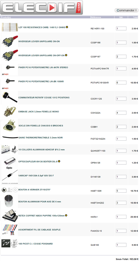
Alors le total peut en refroidir certains. Mais quand on commence à brancher le tout sur des pédales d’écho, saturation (lampe ou transistor), flanger… toujours en analo, ça sonne super
J’attends quelques semaines avant de me remettre à un projet de ce type. Car il faut compter 1 à 2 mois de travail, donc j'organise mon planning de ministre
vass-m : La Volca bass me branche vraiment. J’ai quelques idées, comme lui ajouter un mini clavier 25 touches et une saturation légère en sortie. Et si je trouve les infos, j’aimerais pouvoir lui coller un écran digital avec une Rom pour sauvegarder des Presets.
Enfin bon, il me faudra l'ouvrir avant de savoir ce qu'il m'est possible de modifier.
Ours303
Cela peut m'intéresser, les ref sont des ref fabricant ou magasin? Histoire de trouver les choses ailleurs.
Sinon as-tu réglé le problème des sons voisins que l'on entend un peu sur les pistes individuelles séparées. J'avais essayé de trouver une solution et j'avais jamais trouvé, sur le mien on entend toujours un petit son fantome du kick sur la partie HH par exemple.
profx
Pour ce qui est des sons voisins. Je ne m’en suis pas préoccupé. Mais d’après le schéma, la façon la plus simple serait de mettre un interrupteur avant R32, R48, R53 et R68 pour éviter tout retour.
Exemple, tu veux utiliser la sortie jack HH Out, tu coupes juste avant R32 (interrupteur). Ainsi tu n’auras pas les autres signaux traversant dans le sens inverse cette résistance.
marmad
Pardon my English, but no, this is absolutely incorrect. The potentiometer is to adjust the bias current of the differential amplifier of the VCA. All you will accomplish by changing the potentiometer is to reduce the overall volume of the synth while increasing the volume level of clicks and pops. The "level" pot for the VCA comes before the mixer with the rhythm, so you can adjust the mix that way. Watch my video.
And here are some simple schematics to use the drum mod points with pots for a full range of settings:
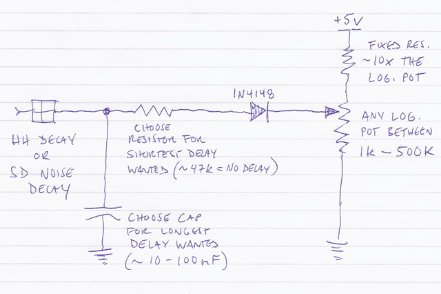
The DECAY circuits (HH / SD NOISE):
Parts (for each circuit):
1x 1N4148 diode
1x log. potentiometer - any size between 1k - 500k, as long as you have a fixed resistor that is 10x larger.
1x resistor - 10x the size of the pot you use; e.g. if you use a 10k pot, you need a 100k resistor.
1x resistor - for the shortest decay you want. If you want zero decay (no volume) at one end of the pot, ~47k should work.
1x capacitor - for the longest decay you want. Perhaps 10 - 100nF, but you can experiment by just holding the cap from the labelled point to GROUND while listening to the rhythm at the slowest possible tempo. Make sure to listen via headphones (or line out) when testing.
Explanation:
The potentiometer sets the bias for the connected diode, thus determining the time at which the timing capacitors will discharge through it - from immediately (no sound) to never (maximum decay). The fixed resistor limits the maximum voltage at the pot wiper to the approx. drop of the diode.
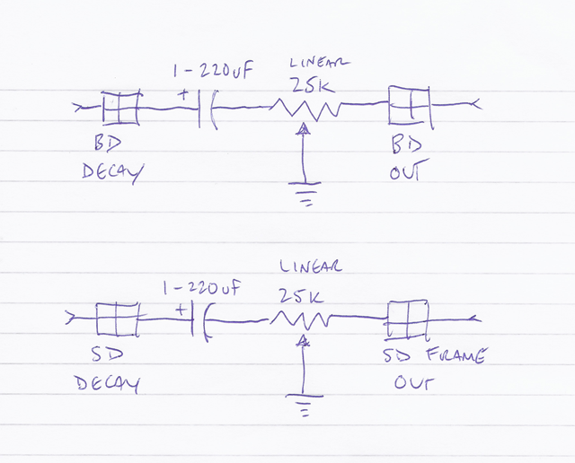
The GAIN circuits (BD / SD FRAME):
Parts (for each circuit):
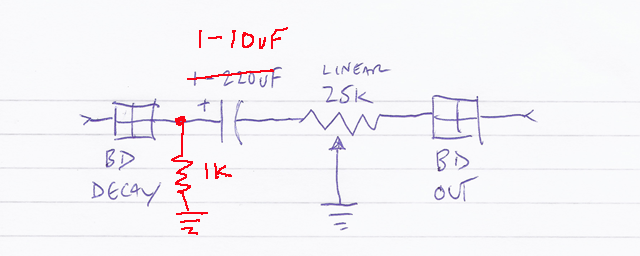
1x 25k linear potentiometer
1x capacitor - to set the bypassing (AC gain) of the respective amp. Perhaps 1uF - 220uF (I've been using 220uF for the BD, but I haven't experimented with SD FRAME yet), but you can experiment by just holding the cap from the labelled point to GROUND while listening to the rhythm. If you use a polarized cap, make sure the + side is to the labelled point. Make sure to listen via headphones (or line out) when testing.
Explanation:
The potentiometer forms a bypassed gain adjust for the respective amplifier. Turning the pot changes the amount of bypassing as well as the gain - from zero gain (no sound) to unbypassed gain (approximately the stock Korg sound - middle position) to completely-bypassed full gain (the sound with the added cap).
One other variation on the gain circuit that can be used to alter the tone of BD (and SD) more, is to increase the gain of the amp before bypassing - as in the following schematic. If you do that, you need to decrease the bypass cap to avoid oscillation (in my test, I lowered it from 220u to 10u).
[ Dernière édition du message le 07/07/2014 à 14:30:57 ]
profx
Dès que j'ai un moment, j'ouvre la monotribe pour tester tout cela.
- < Liste des sujets
- Charte


